Home › Forums › Forum › MTK Kit Builders › Power transformer wiring for 120 V
- This topic has 1 reply, 2 voices, and was last updated 2 years, 3 months ago by clambton29.
-
AuthorPosts
-
January 27, 2022 at 3:05 pm #13734Jesse CurranParticipant
Power transformer wiring for 120 V
Primary side it has orange gray red black and a ground of yellow green wire. In your build video you instruct the 220 VBuilders to do a butt splice on the orange and gray wires will where you tie them together and solder and he shrink the connections. I need some clarification on my next step with 120 V…… Red black hot/negative…… Yellow/green to ground. Am I to do a butt splice on the red and black?
January 27, 2022 at 4:44 pm #13735clambton29KeymasterHi Jesse! Let’s see if we can figure out what’s going on here.
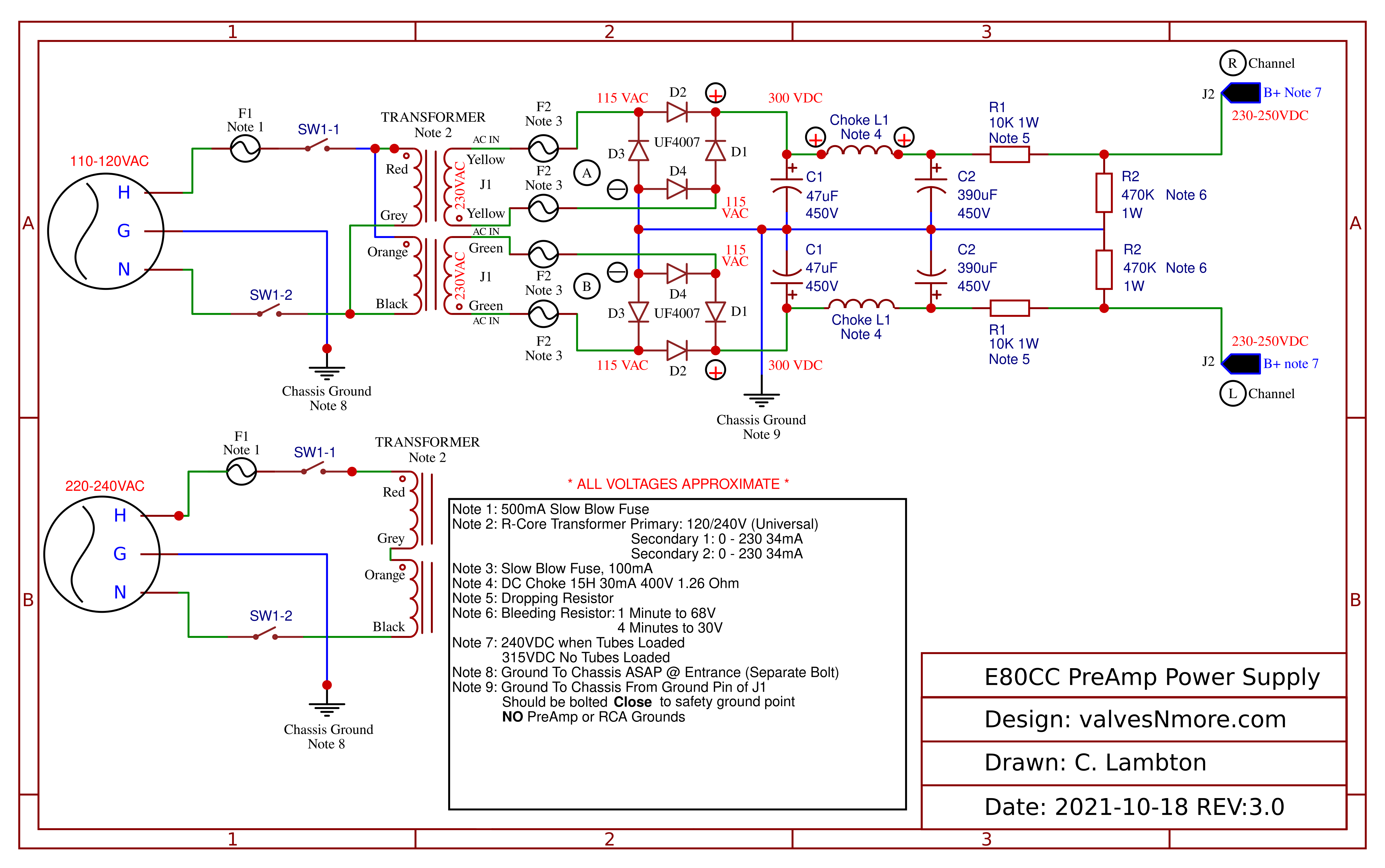
Here’s a copy of the power supply schematic for the E80CC: https://valvesnmore.com/wp-content/uploads/2021/11/Schematic-E80cc-Power-Supply-v3.0-2021-10-23.png
So in the schematic you can see the two sets of primary windings. One set for 110-120VAC and the other for 220-240VAC.
If you look at the 220VAC side, you can see that we go from the switch into the Red wire of the primary. Then out through the Grey wire that is then connected with a butt splice to the Orange wire, then back into the transformer and it comes out through the Black wire and back to the switch.
So that explains the splice for the 220VAC.
Now let’s look up at the 120VAC primary side. You can see the same four wires. But they are connected a bit differently. Instead of making one long primary like you do for the 220VAC side, you split them into two primaries running in parallel. So let’s follow the path.
First you can see that we go from the switch into both the Red wire and the Orange wire. Those wires go into the transformer and return as the Grey wire and Black wire. So we want to tie together the Red and Orange wire. Then we want to tie together the Grey and Black wire.
The yellow/green are the secondary side of the transformer and each set should be going to one of the two power supply PCB boards.
You should be able to follow along at this point in the build video: https://youtu.be/ApUXNIGmW5s?t=1462
And you’ll see Jim tie together the Grey/Black and Red/Orange.
Let us know if there is any more confusion with this. Or if there was something in the build video that threw you off so we can improve it.
-
AuthorPosts
- You must be logged in to reply to this topic.