Forum Replies Created
-
AuthorPosts
-
clambton29Keymaster
Glad to hear you’ve got it up and running and are enjoying the sound Jesse! Let us know what you think once you’ve had a chance to put it through its paces.
clambton29KeymasterHi imnofool,
I’ve just checked and the code is active. Make sure you are typing it in exactly as shown here without the quotes: “cheers10” and that you are purchasing $100 or more before discount and shipping in order for the code to be applicable.
If you’ve double checked that and it still isn’t working, please message us directly using the contact form and we’ll help you get it sorted out.
Thanks,
CharlesFebruary 18, 2022 at 5:57 am in reply to: Soldering wires to RCA Jacks Horizontally instead of Vertically #13857clambton29KeymasterHi Brian,
Thanks for sharing your observation. I’m going to go through the build videos and add notes at the appropriate points to share your advice.
Charles
clambton29KeymasterThanks marchunter. This is my first kit build and I really enjoyed it. I’m looking forward to doing some listening and building and developing some more. We’ve got plenty of interesting stuff on the way!
clambton29KeymasterAnd I’m done! what a build!
I missed a few pictures unfortunately but everything went fairly smoothly. There were a few small hickups along the way that are going to inform on the main production run. Mainly supplying more of a few lengths of wire and some spare parts just in case.
Here it is all wired up and getting its first voltage test:
Voltages all looking good, just a touch high but so is my house wiring (Reading between 120-124vac at wall).
Time to pop some tubes in!
ahh look at that glow! Gotta love the first filament light.
And here are some shots of the done amp:
Now unfortunately I can’t actually listen to it, as it’s other half is currently on the other side of the country. But I’ll give my thoughts on the sound first chance I get. Though I listened to its prototype cousins quite a bit and loved it.
clambton29KeymasterHi Jesse,
Actually Jim thinks it should be replaced. We can send you off a new one if you like. Did it start rotating freely after soldering it? or re-doing some solder work?
And is it just the one jack that’s damaged?
clambton29KeymasterHi Jesse, Once you have the center post soldered up, there should be no more movement in it. And it’s likely that after you start using it, and the center pin on the RCA cable is inserted, it will expand the center post and prevent most of that movement. The only possible issue I could see with that is if you are pushing in the RCA cable ends and then twisting them back and forth after inserting, and even then I highly doubt it will cause issues.
I’d recommend building with them as is, and if you have issues with the jacks from that point then we can ship you a replacement or you could order a new one for yourself. But I doubt it will be an issue.
clambton29KeymasterHi Jesse,
While the bare copper wire would technically work, the tinned wire is going to be far superior for getting good solder joints. And since this is for the grounds it’s going to be very important. we’re putting a length of it in the mail today shipped priority.
You should be able to continue with the build then circle back to the ground wires when it comes in.
Charles
clambton29KeymasterHi Jesse,
I just had a talk with him about this earlier! I was cutting it very close with my build but managed to make it work. For future kits we’re going to try to include more of each of the items that need to be cut/sized by the builder so there’s more leeway for variance and mistake.
Let us know what you need for length and if you need anything else and we’ll ship it out to you ASAP.
Charles
clambton29KeymasterUpdate! Making some great progress. My transformers have been prepped, I’ve mounted everything to the plate and started soldering.
It’s really going together quickly now. I’m thinking one or two more build sessions and it’ll be ready to power up. I’m excited!
clambton29KeymasterSounds good! Best thing you can do when things start going wrong is to slow down or step away for a bit and then come back with a clear head.
Let us know how it goes on Monday!
clambton29KeymasterHi Jesse,
Don’t stress! It happens. Soldering mistakes are just a part of soldering. Can you send us a picture of the board as it is?
There are a number of image sharing sites available, one of the most common is imgur : https://imgur.com/
You can upload a photo there and share the link in a reply for us to take a look. If that doesn’t work, let us know.
In general though it’s very hard to do so much damage that you can’t undo it. Even in cases where you accidentally take a pad off, as long as it’s a through hole there should be one available on the other side and a good solder joint can still be made.
Some tips for removing solder/reworking:
The solder sucker works best when there’s a decent amount of solder to “grab” onto, or form a seal. When removing solder, it’s usually best to add a bit more first. Then you want to make sure the solder is thoroughly melted, going a little bit hotter here than the initial work can help with that. You really need two hands for this job, so make sure the board is secured somehow. If you don’t have any way to clamp it, then try using some tape to tape it down to a table or work surface.
My process for removing the solder would be as follow:
1. Secure the board so I can use both hands freely
2. Apply fresh solder to the joints that I wish to remove, adding maybe a bit more than usual if I’m having trouble getting in with the solder sucker
3. Turning the heat up just a touch on the iron, heat the joint you wish to remove the solder from and hold for a couple of seconds after it’s fully liquified
4. With your other hand, bring in the solder sucker quickly as soon as you pull the tip of the iron back. Try to push the solder sucker tip down so it fully covers the joint and forms as good of a seal as possible with the PCB
5. Immediately release the piston to suck up the solder
6. Repeat steps on remaining joints until the majority of the solder is removed from all connections (you likely won’t get it all, that’s okay)So now you have a component with the majority of the solder removed from around its pins. It should be very close from releasing. At this point you want to start at one end of the pins and using your iron with just a touch of fresh solder on the tip, heat the pads while gently pulling on the component from the other side. You get some movement, then you move to the next pin and repeat, then work your way back across. You should be able to slowly rock out the component millimeter by millimeter till it releases.
Be careful about damaging the component you are trying to remove, and don’t pull too hard. You don’t want to pull the pads off the board. Gentle slow progress is what’s needed.
What you should end up with is a removed component and a PCB with a bit of solder on the pads left over. Go back over those pads with new solder and the sucker to clean out the holes. Remove any excess solder from the components pins. Then re do the work with everything going the right way.
Other things that may help: Applying extra flux to the pins/pads. And a product called “Solder Wick” designed for doing solder removal. It’s exactly what it sounds like, a woven metal wick with a flux coating. You press it onto the pin or pad with your iron tip and the solder gets sucked into the wick. This isn’t great for big jobs, but can help with small ones and cleaning up after a lot of removal with the sucker.
Let us know if that helps and if you need some more help or advice with it. And don’t worry about the mistake! Rework is just a fact of soldering, everyone has to do it.
clambton29KeymasterHi Jesse! Let’s see if we can figure out what’s going on here.
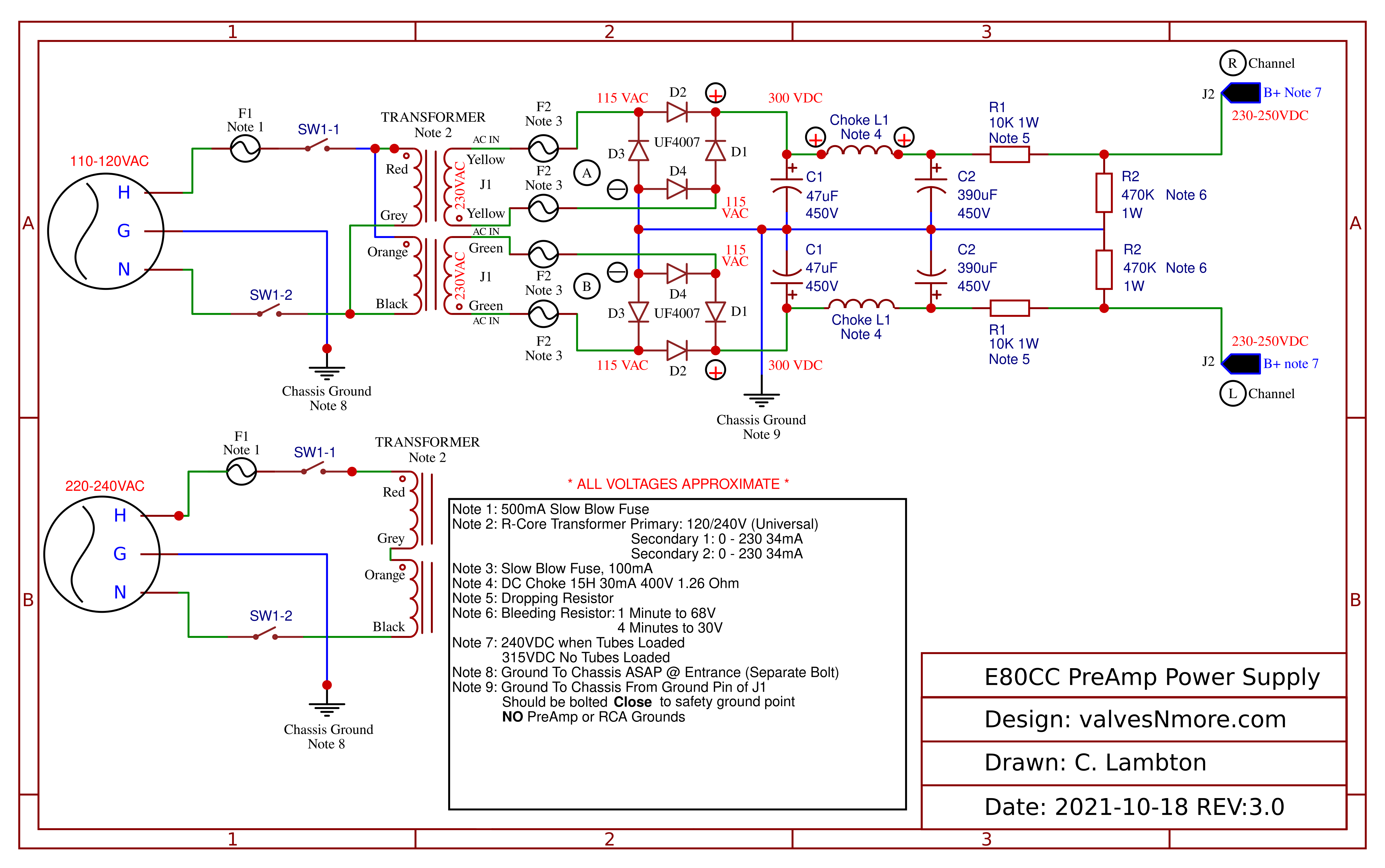
Here’s a copy of the power supply schematic for the E80CC: https://valvesnmore.com/wp-content/uploads/2021/11/Schematic-E80cc-Power-Supply-v3.0-2021-10-23.png
So in the schematic you can see the two sets of primary windings. One set for 110-120VAC and the other for 220-240VAC.
If you look at the 220VAC side, you can see that we go from the switch into the Red wire of the primary. Then out through the Grey wire that is then connected with a butt splice to the Orange wire, then back into the transformer and it comes out through the Black wire and back to the switch.
So that explains the splice for the 220VAC.
Now let’s look up at the 120VAC primary side. You can see the same four wires. But they are connected a bit differently. Instead of making one long primary like you do for the 220VAC side, you split them into two primaries running in parallel. So let’s follow the path.
First you can see that we go from the switch into both the Red wire and the Orange wire. Those wires go into the transformer and return as the Grey wire and Black wire. So we want to tie together the Red and Orange wire. Then we want to tie together the Grey and Black wire.
The yellow/green are the secondary side of the transformer and each set should be going to one of the two power supply PCB boards.
You should be able to follow along at this point in the build video: https://youtu.be/ApUXNIGmW5s?t=1462
And you’ll see Jim tie together the Grey/Black and Red/Orange.
Let us know if there is any more confusion with this. Or if there was something in the build video that threw you off so we can improve it.
January 27, 2022 at 12:17 pm in reply to: Coaxial RCA Cable and Braided 8 Gauge Speaker Wire Solution for Noise #13733clambton29KeymasterThat’s interesting Brian! I wonder at what point in the chain the unwanted signal was getting inserted. Clearly something was acting as an antenna but the input stages on the amps should have been filtering that out. Did you do any testing to identify where it was coming in?
January 24, 2022 at 1:04 pm in reply to: Screen Shots From Jim’s Youtube episodes Help Visualize E80cc Preamp Build #13726clambton29KeymasterHi Brian! That’s great advice. For anyone doing this on a windows computer, this is called a “Print screen” and there are a few different ways of making one. You can make a print screen of everything on your screen by simply holding down the windows key and hitting the “Print Screen” button on your keyboard. You can find the saved screenshots under your pictures then screenshots where you can view, edit, or print it. You can also use the Microsoft Snipping Tool in Windows to copy only part of the screen in the same way and save it directly.
Personally I like to use a combination technique. There is an excellent free program called Greenshot that replaces the default print screen functionality in windows with a better version of the snip tool. I can very quickly take entire snapshots or small portions and save, print, or edit them as needed. There’s a link to it below.
How to use the Microsoft Snipping Tool:
How to use print screen:
https://www.howtogeek.com/226280/how-to-take-screenshots-in-windows-10/
Hope this helps, and thanks for adding to the forum!
-
AuthorPosts